Science and Technology Center
Coppin State University │ Baltimore, MDNicholas Zitterbart
Construction Management
Building Statistics |
|||||||||||||||||||||||||||||||||||
Part I Building Information
Project Team Owner │ University of Maryland │ www.umd.edu
Architecture
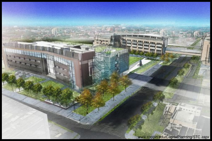
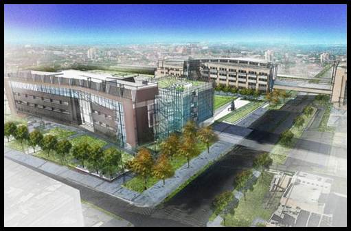
Images Courtesy of www.coppin.edu/CapitalPlanning/STC.aspx The New Science and Technology Center (STC) is located on southern end of Coppin State University’s Campus in the northwest suburbs of Baltimore, Maryland. The Project requires the demolition of approximately 210 residences on the south side of campus. After rough grading and the installation of a rammed aggregate pier system, the new 4-story concrete building will be constructed providing for the critical needs in science related disciplines on campus. It will include classrooms and areas for the Departments of Mathematics and Computer Science and Natural Sciences as well as the Information Technology Division. In comparison to the rest of the CSU campus, the architectural design of the STC includes sleek lines and a modern façade. The surrounding area buildings have typical brick facades with rectilinear building footprints. With this new design, the glass curtain walls add a modern and lively touch to the campus while still tying into the existing brick architecture. The new building is situated to the east of the new state-of-the-art Health and Human Services Building, which has very similar architecture. These buildings as well many others are part of Coppin State’s mission of expanding and creating a more attractive campus environment.
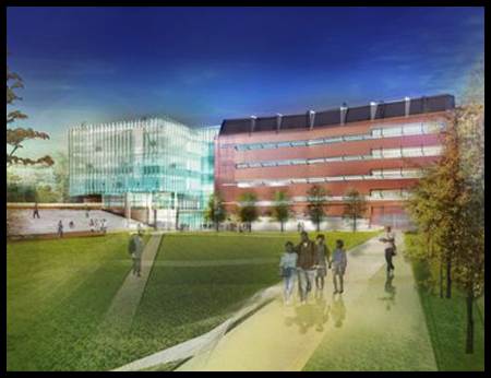
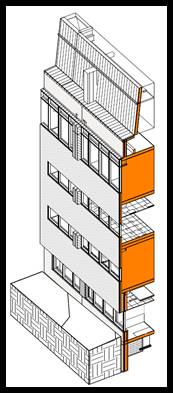
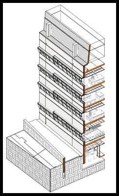
Building Enclosure Major components of the building enclosure include a large glass curtain wall façade on the north end while a brick façade accents the main building structure. The square offset glass curtain wall on the north end attracts the viewer’s eye to the building and opens to the grassy quad on the east side. The sections below show greater detail of the building’s enclosure and the materials that are being used.
Sustainability The Science and Technology Center is required to reach a minimum of LEED Silver Certification, but is tracking to achieve LEED Gold Certification with the current design. Some LEED categories include the site location, water efficiency, energy consumption, recycled material, and indoor air quality. The site is in an urban area where public transportation can be utilized and the open quad area preserves pervious surfaces. The low-E glass mentioned earlier will help reduce energy consumption as well as the variable speed drives of the mechanical systems. In addition, the project has a goal of recycling up to 75% of construction waste. Furthermore, particular sustainable devices integrated into the building design include a rainwater collection system, a green roof, sun shades, high efficiency boilers and chillers, and a complex insulation backing system behind the metal panels to minimize thermal bridging.
Part II
Construction The Science and Technology Center is under a strict construction timetable due to initial project delays that pushed construction back almost 3 months. Approximately 210 row homes stood in place where the new building would stand. It was through property acquisition issues that caused the initial large delay. More than half of these properties were found to have asbestos-containing material and abatement and clearing procedures were planned. This delay put pressure on the project team to find areas in the schedule for acceleration and using different means and methods. As the original schedule outlines, the building will be constructed with two phases—North and South—and progress upwards through the four floors and penthouse. With the building in the early stages on construction, opportunities for schedule acceleration will be of high importance—the exterior envelope construction methods will provide chances to gain back schedule time. A foreseen constructability challenge includes the intense waterproofing details in many areas. These include the thresholds where materials change types and also at the top of the curtain wall near the parapet. The waterproofing membrane and air barrier require integration between installation of two different systems, and consequently two different subcontractors. These areas should be of high focus to eliminate any future maintenance issues with the building envelope. In addition to the waterproofing detail, the curtain wall and masonry wall construction deem another constructability issue in terms of schedule duration. A stick-built system of 2” HSS connections, aluminum frames, and 1” glazing will be one of two items on the schedule that endure the most installation time—the second being the masonry wall construction. As the project progresses, these areas can be the focus of major cost and time savings with alternative installation methods.
Electrical The main building switchboard is rated for 4000A, 480/277V at 3 Phase. It is with this that 6 transformers supply power to the building. The lower level main transformer is a general duty dry type transformer with an integral USS rated at 2500kVA. From this branch, four other transformers supply each of the floors 1-4. The remaining transformer is located at the lower level. The main building load was designed for 3,066,675 VA and 3690 amps. In addition, the emergency power system is supplied by two generators (750kW and 500kW).
Lighting The lighting plan for the STC Building involves a combination of compact fluorescent down lights, different sizes of T5 fluorescent troffer luminaires, and wall mount pendant fixtures. The main lobby utilizes a majority of suspended direct linear fluorescent F28T5 luminaires with a single lamp. When looking at the typical classroom and lecture hall, a linear direct/indirect pendant type luminaire with F28T5 lamps. For a majority of the lab spaces, a 2’x4’ high efficiency recessed troffer luminaire is utilized with 3-F28T5 lamps. The general spaces on the lower level and storage areas impose 4’ surface-mounted strip industrial reflector luminaires. The typical lamp type throughout the entire building is a F28T5.
Mechanical This building is supported by 6 different VAV Trane air handling units (AHUs), 4 cooling towers and multiple boilers, lab exhaust fans, and computer room air condition units. This is due to the mixed-use of this facility and has many requirements to fulfill. There are three large AHUs with total CFM ranges from 23,500-44,500 that serve the building’s main floors. The remaining 3 AHUs with total CFM ranges from 3,200-4,500 serve the lower levels and the lecture hall area. Being that a large portion of this building is represented by laboratories, there are a major number of exhaust fans to serve each of these areas. Also, fin tube radiators supply supplemental warm air along the window line of each space to aid the central AHU. Much of these systems also include areas for schedule acceleration due to the system type and installation labor necessary.
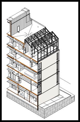
Structural The structure of this building is supported by foundation walls (12” to 24” thick) and spread footings (5’x5’ up to 14’x14’) bearing on suitable soil on the north end and geopiers on the south. The geopiers on the south end support loads ranging from 80 kips to 980 kips, depending upon location on the building footprint. The cast-in-place structure for the floors 1-4 incorporate elevated concrete slabs supported by concrete beams and columns. The concrete columns range from 20”x20” to 28”x28” square columns and 32” diameter circular columns. The concrete beams supporting the slabs have various sizes ranging from 16”x24” to 30”x48”. Elevated concrete slabs are to be 12” thick normal weight concrete reinforced with #4 rebars at 9” on center as top and bottom mat bars. A thickness of 8” (20” total slab thickness) at locations of drop panels around the columns is required. Structural steel is then used for the design of the penthouse above the fourth floor. Composite metal decking will top off the structural frames and provide the support for the roof system. Typical beam sizes include W14x22 and W16x26. A typical roof frame utilizes W14x61 columns (20’ in height) and W18x35 beams (~25’ in length). The stairwells and partials floor space also include structural steel members. In total, the steel bid package was estimated at $750,000.
Fire Protection The entire building, including all mechanical and electrical rooms is protected with a fully automatic combination standpipe-sprinkler system (Class 1). In addition all unconditioned spaces subject to temperatures less than 40°F will be protected by a dry-type sprinkler system. Sprinklers will also be supplied at the top and bottom of elevator shafts. The campus datacenter, the main distribution frame telecommunication and electrical room #3 will be protected with a fully automatic, total flooding clean agent fire suppression system. The room enclosures will also be protected with a single-interlock preaction sprinkler system.
Security & Technology The Science and Technology Center will integrate new door/gate access controls (card) and intrusion detection through video surveillance (CCTV). This will include the installation of the following items: fiber optic cabling and patch panels, network video recorders, uninterruptible power supply, and a single monitor computer for control of the system. In addition to these security items, many of the rooms will be supplied with projectors, screens, and multiple computer stations. This will provide the newest technology for students on campus and will serve as the main computer labs. |
Note: While great efforts have been taken to provide accurate and complete information on the pages of CPEP, please be aware that the information contained herewith is considered a work‐in progress for this thesis project. Modifications and changes related to the original building designs and construction methodologies for this senior thesis project are solely the interpretation of Nicholas Zitterbart. Changes and discrepancies in no way imply that the original design contained errors or was flawed. Differing assumptions, code references, requirements, and methodologies have been incorporated into this thesis project; therefore, investigation results may vary from the original design.